Water Level Indicator Using Magnets
Introduction: Water Level Indicator Using Magnets
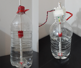
I have been thinking and researching about measuring water because I needed it for my next projects.
Most common way is using the water as a conductor, so if there is water between 2 wires you will get the close circuit, but main problem on conductive indicators is the water must have salts cause that's what gives the water the conductivity and that wasn't working for me because one of my projects was to have an alarm inside my disposal bottle of my air conditioner when it was full but since that water is from condensation it has no conductivity at all :(
A mechanical way is another option; we all have seen that inside our bathrooms, almost every toilet flush system works with a mechanical switch which consist in a buoy that closes the water entry. This method was a good approach but I wanted to keep my current simple bottle without having to create huge modifications on it by cutting it out and then having to seal it.
That's when I came across those simple buoy switches that uses Reed Sensors inside; keeping in mind that I wanted a simple solution I came up with this concentric pipe which holds reed switches inside it and has a moving buoy with magnets attached.
Step 1: How Does It Work?
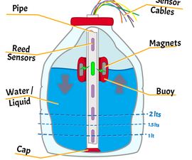
First thing to understand: what is a Reed Switch?
The reed switch is an electrical switch operated by an applied magnetic field.
A buoy (which has magnets inside it) will float in water which means it will be keeping magnets at water level and since we have a Reed Switch (at some specific height inside the pipe) it will be activated (closing or opening the circuit) and if we know how many liters are at that height we know how much water is in the bottle.
An important thing, there is cap at the bottom of the pipe because we don't want water to be inside the pipe, the main idea of this method is to not use the conductance of the liquid to measure. Having water inside the pipe could lead into false indications by bypassing a reed switch.
I went a little overkill here with the amount of reed switches, my first idea was to test this method by placing a reed switch per liter (distance of 5 cm in that bottle) and I could tell the half state by getting 2 sensors activated at same time, so in short I could know every half liter the water level.
You don't need to go that precise, you can put 1 or 2, at bottom and top to know if is full or empty, the cool thing is you can get a switch at any level you want without destroying the bottle!
Step 2: What You Need
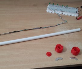
Bottle
Check the buoy size first cause it has to go through the bottlemouth - this buoy has a 30 mm outer diameter
Normally a family bottle of water should work (5 or 6 liters). A drum is another option but I suggest you to get a transparent one for simplicity of testing it.
Pipe
For this 3d printed buoy it has to be smaller than ~14 mm outer diameter.
Since you need to place reed switches inside so for this 3d printed cap to work in needs ~11 mm inner diameter but you can seal it with any other thing really.
Length doesn't matter, I would say to be bigger than your bottle height.
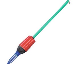
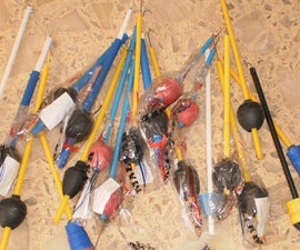
I've got my pipe from a local store buying a cheap and crappy toilet universal flush system (attached photos of them)
3D Printed parts
- Buoy (it has 2 equal parts)
- Cap
Here are the parts and how to print them: https://www.thingiverse.com/thing:2541017
Electronics
- Reed Switches I used NormallyOpen (NO): get as many as you want but get a couple more of what you need cause they may break by manipulation
- LEDs (5 mm) these are mainly for easy testing signals but you can use an arduino or anything you want
- Resistors (330 ohms) - if you go with leds you're gonna need protective resistors (so one for each led)
- Cable, I recommend you to use Cat5 cable, its the commonly known as networking cable. It has 4 pairs inside and they are pretty rigid so they work well for this reed-switches-inside-a-pipe application
Magnets
Well here is more a try an error really, I don't have the math for a good magnet vs reed switch ratio.
The only restriction is size cause it has to fit inside the buoy which has 4 places of size 2 mm x 10 mm x 15 mm height. If you're buying magnets I recommend you to have the buoy in your hand first.
I used magnets taken from an old hard drive breaking just one will give you the 2 magnets needed here which I later split each at half having a total of 4.
A note: notebook HDD magnets didn't work for me I guess they don't have enough strength, so use a desktop pc HDD magnets
Tooling
- Hot glue gun for gluing + sealing (if you have a better solution for this please put a comment!)
- Solder iron, soldering tin and some isolation tape or heat shrinkable for reed switches connections inside the pipe
Step 3: Tying Reed Sensors Together
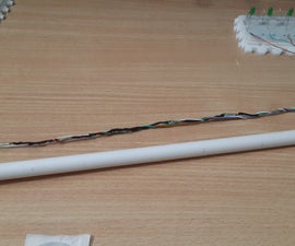
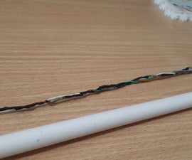
Connections here are pretty straight forward, one common cable for all reed switches and another on each end, if you choose to use 5 reed switches you will end up having 6 cable ends.
What I did was to get a network cable and took 6 cables from inside (they have 8 in it). Measure the height you want to get your reed switches at and solder them like the picture trying to keep them vertical along with the cable, so it will be easy to insert into the pipe.
For my experiment I've used 5 switches at 5 cm of distance from each since for this Bottle each liter is 5 cm of height.
Step 4: Building the Buoy
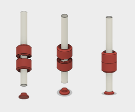
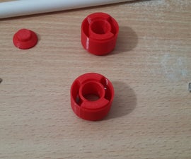
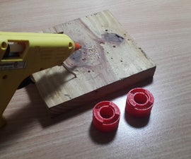
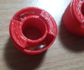
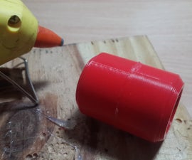
I have placed instructions on each pic here, the most important thing is to seal the buoy since we need air inside for it to float so don't be cheap on the hot glue and fill every gap on outside
Step 5: Building the Pipe
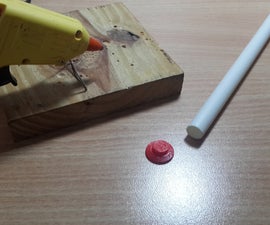
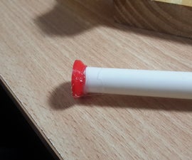
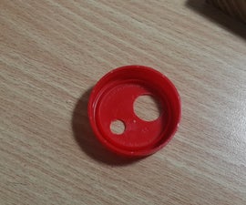
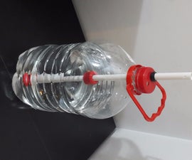
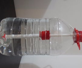
Placed instructions on each pic, here some tips:
- It's a good idea to do 2 holes in the bottle cap so you can put and take water to test.
- Pipe cap may not be necessary, I think a good amount of glue will do the job BUT the cap also works as a trap-end for the buoy so take that into account
- Since the pipe will have air inside water will push it up which will take it away of the bottom. To fix this I used a rubber that came with the flush system kit from where I took the pipe, another option would be to fix it to the bottle cap using glue
Step 6: Getting Some Test Signals - LEDS
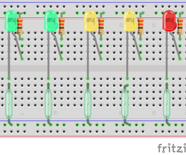
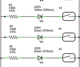
Our final step is to get a visual signal for testing the device, it can be anything I've chosen leds cause it's the easier and faster way of doing it, but normally this is a first step to a bigger project where we will be doing something with that signal and a led won't help much in there.
Step 7: Testing It All Together
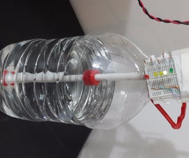
So here we are, a simple level indicator using magnets. From here there are countless things you can do with it, the only thing I do not recommend is to drink this water since it will be in contact with glue and 3d printed plastic, but there are many other things to try and play, I'll be working on some projects using this, if they make sense to share I'll be creating a second instructable.
If you build one yourself, please share it on the comments with a photo. Any questions and ideas are welcome!


